
Watchguard Example 1 | Watchguard Example 2
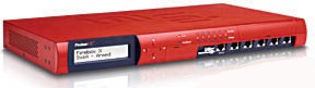
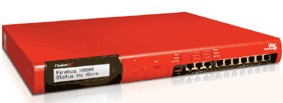
A production test fixture was needed for this device.
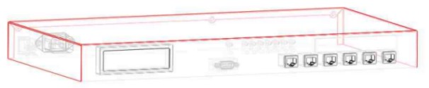
Mechanical drawings of the device were not provided, and the device had to be scaled and modeled, before fixture design could proceed.
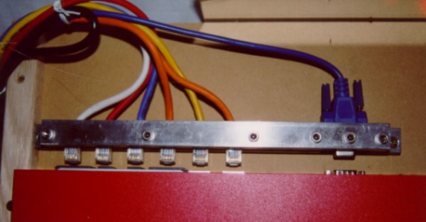
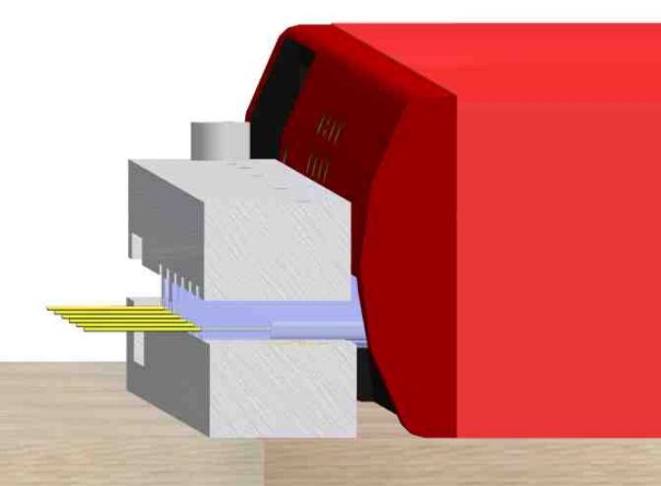
A functional test fixture with RJ45 and DB9 connector clamp and guides for the device under test. This view is from the back of the test fixture with inspection mirror removed showing the front of the device under test with front bezel removed. The side guides are made of hard wood to not scratch the paint on the device cover. The latching barb on the RJ45 connectors are also removed.
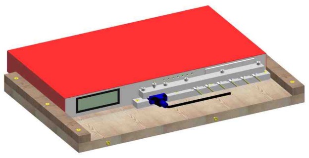
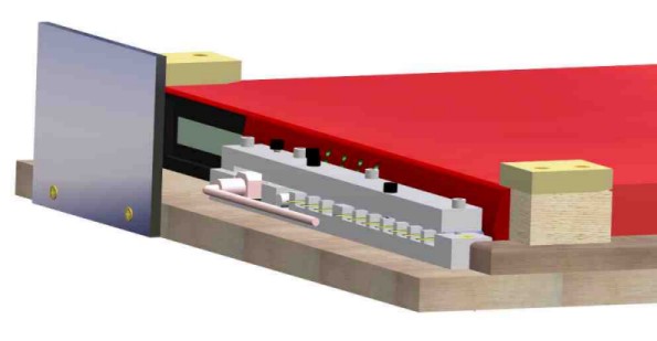
Top view of test fixture.
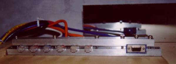
Front view of test fixture with visual inspection mirror in place.
Front view of test fixture with mirror in place.
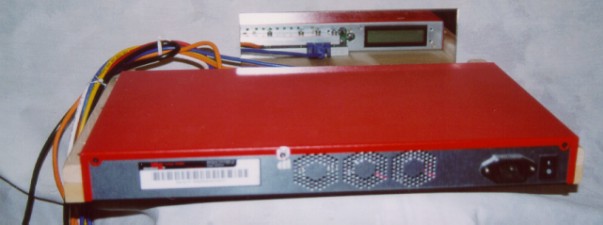
The bezel could not be installed during test, as the RJ45 and DB9 connector clamp would interfere
with the bezel. Later WatchGuard determined that the bezel must be installed for the test, and a new
connector clamping scenario was needed. At issue was the short length of an RJ45 connector and close
proximity of the bezel. The solution was to remanufacture the RJ45 connector to have enough length
for the clamp to grip the connector.
A molding tool was made to lengthen the RJ45 connectors with urethane, and the original clamps were
reworked to hold the remanufactured RJ45 connectors.
Urethane mold tool in action.
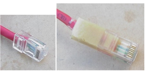
RJ45 connector before and after remanufacture.
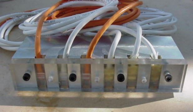
Test fixture with device and bezel with reworked clamp and remanufactured RJ45 connecot cables.
The next generation of the device.
The next generation of the device test fixture using the remanufactured RJ45 connectors. This generation is deeper than the first and had some mechanical variances that required extra guides into the test area.